Friday, September 27, 2013

NOR Gate

The NOR Gate is a combination of a NOT Gate and a NOR Gate. In this gate every input that is both 0 would result in an output of 1. Everything else would have a an output of 0. The breadboard below indicates the gates of 11, and 12 connected to the the GND which will result in an output of 1. The output is connected to gate number 13 which then linked to the LED which must be lighted on. Thank you for the pictures of Chapter 4 Presentation.  


NAND Gate

The NAND gate is a combination gate of a NOT gate and a AND gate. Every output of a NAND gate is 1 except when both inputs are 1 so the output would be 0. In the breadboard below the inputs are both connect to the GND which are connected to gates 13, and 12. The output which is 1 would be connected to gate number 11 to the LED, which is lighted up in this case. Thank you for the pictures of Chapter 4 Presentation. 


XOR Gate

The XOR gate uses 2 inputs, for every input that is the same the output will always be 0 but if the input is opposites the output would be 1. The XOR is a combination of an OR gate which the full name is called exclusive OR. They differ in when way where in an OR gate if both inputs are 1 the output would also be 1, but in a XOR gate the output is 0. The breadboard below shows the connection of gate 13 to the GND, and gate 12 to the VCC. The output (11) is then linked to the LED which will receive an output of 1, so the LED needs to be on. Thank you for the pictures of Chapter 4 Presentation.


OR Gate

Same as the AND Gate the or gate has two inputs but in this case its the opposite from the AND gate. With any input that has a value of 1 the output would be 1. Only if both inputs are 0 the output would be 0, according to the boolean expression. Below in the breadboard, gate 13 and 12 is connected to the vcc so the input is 1, so gate 11 will have an output of 1, which is connected to the LED that is lighted on. Thank you for the pictures of Chapter 4 Presentation.


AND Gate

The AND gate has two inputs rather than one input like the NOT gate. The output can only be 1 if both the input and the output is 1. Any other combination the output would be 0, according to the boolean algebra. In the breadboard below, the LED is on gate 13 and 12 are both connected to the vcc which is an input of 1. The output would be 1 so the gate number 11 is connected to the LED. Thank you for the pictures of the Chapter 4 Presentation. 


NOT Gate

A NOT gate in other words the inverter shows the result in an opposite way. If you input a 1 (vcc) the result would be 0, just like the picture below using the breadboard, the cable signal is connected to port 13 and the output is connect to the LED, in which in this case its off because the input is 1 so the output must be 0. Thank you for the pictures of Chapter 4 Presentation.

Tuesday, September 24, 2013

Boolean Logic Diagrams

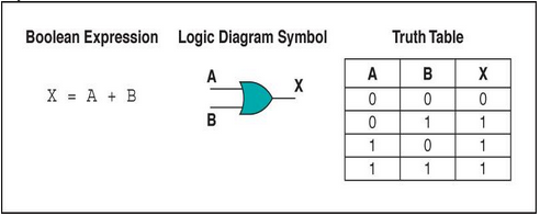
This is the OR gate for the Commutative Property showing that A + B = B + A meaning that the two inputs are added together. For example if A = 1 and B = 0 the output would be 1.

A
B
X
0
0
0
0
1
1
1
0
1
1
1
1


This is the AND gate for the Commutative Property which shows AB = BA meaning that the two input are multiplied together. For example if A = 1 and B=0 the output would be 0.

A
B
X
0
0
0
0
1
0
1
0
0
1
1
1


This is the AND gate for the Associative Property showing that (AB)C = A(BC) meaning that A and B are multiplied together to receive AB then C is added to the result to form (AB)C. For example if A = 1, B = 0, C = 1. AB would be 0 and then (AB)C would also receive a 0.

A
B
C
X
0
0
0
0
1
0
0
0
0
1
0
0
0
0
1
0
1
1
0
0
0
1
1
0
1
0
1
0
1
1
1
1


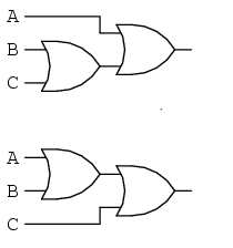
This is the OR gate for the Associative Property showing that (A+B) + C = A + (B+C) meaning that A and B are added together to receive A +B then C is added to A+B. For example if A = 1, B = 0, and C = 0. A+B would be 1 and A+B+C would be 1.

A
B
C
X
0
0
0
0
1
0
0
1
0
1
0
1
0
0
1
1
1
1
0
1
0
1
1
1
1
0
1
1
1
1
1
1


This the AND gate for the Distributive Property showing that A(B+C) = (AB) + (AC). meaning that B and C are added together to receive B+C then an A would me multiplied to B+C using an AND gate obtaining A(B+C). For example if A = 1, B = 0, and C = 1. 1+0=0*1=0 the final output would be 0.
A
B
C
X
0
0
0
0
1
0
0
0
0
1
0
0
0
0
1
0
1
1
0
1
0
1
1
0
1
0
1
1
1
1
1
1


This is the NOT gate for the Identity Property showing that A^1 = A or the inverse. For example if A = 1 the output would be 0 because it would become the inverse.
A
X
0
1
1
0


This is the NAND gate for the Complement Property showing that (A * B)^1. For example if A = 0 and B = 0 the output would be 1.

A
B
X
0
0
1
0
1
1
1
0
1
1
1
0


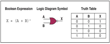
This is the NOR gate for the DeMorgan's Law showing that (A+B)^1. For example if A = 0 and B = 0 the output would be 1.

A
B
X
0
0
1
0
1
1
1
0
1
1
1
0


Tuesday, September 3, 2013

Computing Language basic concepts

Bit: Information that is expressed as the numbers 0 or 1 in binary form, and a form of memory. 8 Bits = 1 Byte or 1 Bit = 0.125 Bytes.

Byte: A group of bits (binary digits), 8 characters because 8 bits = 1 byte that operate in one unit, and a bigger form of memory.

Binary: A language that contains only two digits that include 0 and 1. This is the basic computing language that only a computer would be able to understand. An example can be the number 331, in binary language it is 001100110011001100110001

Denary/Decimal: A numeral language that has a base of 10, which includes digits from (0-9). This is normal type of digits that we use as a base to convert into binary hexadecimal or octal.

Hexadecimal: A numeral language that has a base of 16, which includes digits from (0-F). This language includes the alphabetical letters that continues on from 10-16. An example could be 331 which is 14B in hexadecimal.